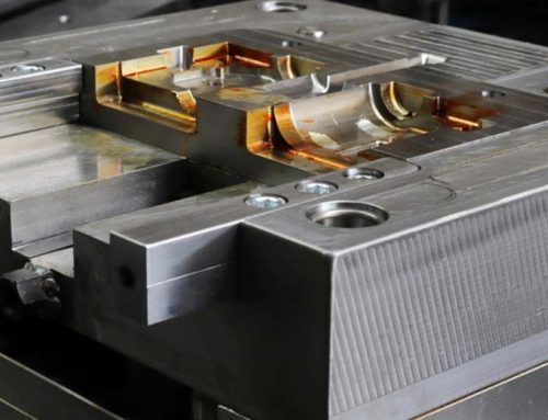
The shape of a plastic part decides whether it can be molded cleanly, how much the mold will cost, and whether the finished part will be strong and free of defects. These 10 geometry tips cover the decisions that matter most when you design a part for injection molding. Get them right, and the mold is simpler, the parts come out cleaner, and the quote comes back lower.
1. Add a Draft Angle
Every surface parallel to the mold-opening direction needs a slight taper, called a draft angle, so the part releases from the mold instead of sticking. A typical draft angle is 1° to 2°, with 0.5° as a minimum. Take the larger value whenever the design allows — the part ejects more easily. Brittle and hard materials need a larger draft; parts that need high precision, or tall parts, need a smaller one. If the draft changes a dimension that has a tolerance, note that on the drawing so the tolerance is checked at the right end.
2. Keep Wall Thickness Uniform
Wall thickness is the first thing a molder checks. It should be as uniform as possible across the part. Walls that are too thin will not fill properly and can deform; walls that are too thick cool unevenly, causing sink marks, bubbles and warping. A typical wall thickness for plastic parts is 1 to 6 mm, and 2 to 3 mm is the most common range. Large parts may need thicker walls, but remember: making a wall thicker does not automatically make the part stronger — it often makes it weaker, because the extra material shrinks and builds up internal stress.
3. Use Ribs Instead of Thick Walls
If a part needs more strength, add ribs rather than thickening the wall. Ribs raise the stiffness of the part without the sink marks and long cooling times that thick walls cause. Keep each rib thinner than the wall it joins — otherwise the joint will sink and show a mark on the outside surface. Thin-walled parts with well-placed ribs are stronger, lighter and cheaper to mold than thick-walled parts.
4. Design the Support Surface Carefully
When a whole flat face is used as the support or reference surface of a part, shrinkage and warping make it hard to keep that face flat. Instead, use a raised rim or several small raised feet as the support surface. The part then rests on small defined points, which stay flat and make assembly more predictable.
5. Round Every Corner
Sharp corners concentrate stress, slow down the flow of plastic, and make the part harder to eject. Round every inside and outside corner you can, with a radius of at least 0.5 to 1 mm. Rounded corners also keep the wall thickness consistent where two walls meet, which reduces internal stress and sink marks — and they make the mold itself easier to machine and longer-lasting.
6. Place Holes with Care
Holes must not weaken the part. Keep enough material between a hole and the edge of the part, and between two holes, so the area around the hole does not crack during assembly. Deep, narrow holes are hard to mold: the core that forms the hole is long and thin, so it can bend or break. If a hole is too deep for its diameter, consider drilling it after molding instead. Side holes are a special case — they need a side core or slider in the mold, which adds cost and complexity, so avoid them unless the design truly needs them.
7. Use Raised Text and Symbols
If the part needs text, a logo or a symbol molded into its surface, use raised characters rather than engraved ones. Raised text is far easier to make in the mold. If the surface cannot have a raised feature, or the text needs paint, put the raised characters inside a shallow recess so they are protected. Keep the character height at least 0.2 mm and the line width at least 0.3 mm — 0.8 mm is usually the most readable — and give the characters a draft angle of more than 10° so they release cleanly.
8. Avoid Undercuts Where Possible
Undercuts — recesses or projections that prevent the part from sliding straight out of the mold — force the mold to use side cores, sliders or collapsible cores. Each one adds cost, complexity and maintenance to the mold. Side undercuts are the worst offenders. If the design does not truly need an undercut, redesign the feature so the part releases in a straight pull. When an undercut is essential, discuss it with your supplier before the mold is designed, because the mold structure depends on it.
9. Design Plastic Gears for Molding
Plastic gears are common in electronics and instruments, but they need molding-friendly proportions. As a guide: the rim width should be at least 3 times the tooth height; the spoke thickness should be equal to or less than the rim thickness; the hub thickness should be equal to or greater than the rim thickness and roughly equal to the shaft diameter; and the hub outside diameter should be 1.5 to 3 times the shaft hole diameter. Round all corners generously to reduce stress, and avoid interference fits between the shaft and the gear bore — use a transition fit instead, such as a keyed or pinned connection. Thin gears warp easily, so keep the section as even as possible, and use the same shrinkage rate for gears that mesh with each other.
10. Design Threads for Plastic
Threads on plastic parts can be molded directly or cut afterwards by machining. Molded threads are cheaper, but their accuracy is limited — do not specify a thread accuracy above grade 3 for a molded thread. Plastic threads are also much weaker than steel threads, roughly one-tenth to one-fifth of the strength, so use a larger thread size than you would in metal and avoid fine threads. Where a thread will be assembled and removed often, or where it carries a high load, use a metal threaded insert instead of a plastic thread.
Design It Right the First Time
Good plastic part geometry is simple geometry: even walls, generous draft, rounded corners, ribs instead of thick sections, and no undercut that is not truly needed. Follow these 10 tips and your part will mold more easily, look better, and cost less to tool.
If you are designing a plastic part and want a second opinion before cutting a mold, send your 3D model. Aluminum rapid tooling is often the fastest way to get real molded parts for testing. Request a quote from Dexin CNC — upload your drawing in STEP or IGES format, and we will reply within 24 hours.